Four Channel Utility Processor

Share on Facebook Share on Twitter

THIS PRODUCT IS NO LONGER IN PRODUCTION.

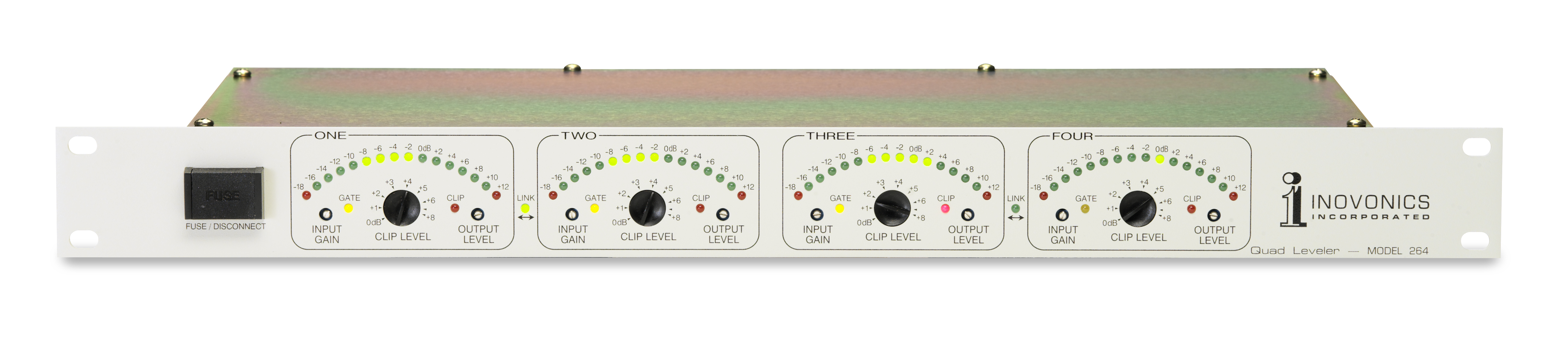
This AGC processor boasts four separate and independent channels of analog audio gain control, which can be used separately for microphone leveling or similar mono applications, or selectively linked for dual-stereo or split mono/stereo program control.

Featuring colorless Class D (PWM) technology for stable and transparent operation, the 264 employs a unique combination of peak and average response to program dynamics, delivering the gain-riding advantage of an intelligent AGC coupled with the tight peak control of a fast limiter.

This combination of long- and short-term level correction normalizes the average-to-peak ratios of diverse audio sources, giving a consistent level of subjective loudness without using excessive, ear-fatiguing compression.

Features


  • THIS PRODUCT IS NO LONGER IN PRODUCTION

  • Four independent channels easily configured as 4 mono, 2 stereo, or 1 stereo and 2 mono

  • Establishes fixed average/peak ratio without overly compressing program dynamics

  • Easy installation and setup

  • Program-controlled and fully automatic operation

  • Alarm tally outputs for remote indication of program source problems

  • Simple and straightforward design for easy maintenance

placeholder

Specifications


Frequency Response

±0.25dB, 20Hz–20kHz

Noise and Crosstalk

Better than 70dB below the nominal program output level, 20Hz–20kHz.

Distortion

<0.15% THD, 20Hz–20kHz.

Program Line Inputs

Active-balanced, bridging (XLR) inputs accept nominal program line levels between –15dBu and +15dBu.

Input Capture Range

The gated-AGC function acts on both the average and the peak program content to normalize input levels between –18dB and +12dB, relative to the nominal, ‘zero-VU’ input setting.

Peak Controller

A closed-loop, time-domain limiter restricts program peak values to a level between 0dB and +8dB, relative to the AGC-leveled input signal. Peak control is based on the limiter’s complex response to program dynamics.

Peak Clipper

A front-panel-adjustable ‘semi-hard’ clipper may be set by the user at any value between 0dB and +8dB, relative to the peak limiter output ceiling. Settings below +8dB will be predicated on acceptable levels of clipping artifacts for the specific program content.

Program Line Inputs

Active-balanced (XLR) outputs; level may be adjusted between 0dBm and +15dBm.

Stereo Linking

To preserve stereo imaging, gain reduction circuitry may be linked between channels 1 and 2 and/or between channels 3 and 4.

Alarm Tally Outputs

Each channel has an open-collector-transistor output that saturates to ground for a program-loss or out-of-limits condition. Tally outputs may be tied together to create a common alarm.

Size and Weight

23” x 16” x 2” (2U); 8 lbs

584mm x 406mm x 51mm ; 3.6 kg