Tuning Range
530kHz to 1710kHz in 1kHz increments; programmed with a DIP-switch under the top cover.
Total Modulation Measurement
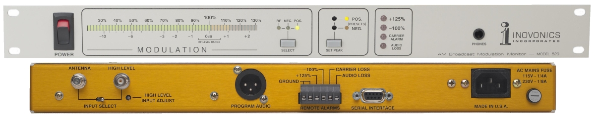
The front-panel bargraph readout is peak-responding and incorporates a “floating” peak-hold display. It may be switched between positive or negative carrier modulation and indicates modulation peaks from 22% to 130% in 2% increments. The display also indicates incoming RF carrier level.
Peak Flashers
Preset “absolute limit” flashers are factory calibrated at –100% and +125% carrier modulation. Separate POS and NEG flashers may be set by the user at values ranging from 80% to 130%.
Accuracy and Calibration
Modulation readings are referenced to the incoming unmodulated carrier level, obviating the need for an internal calibration source. RF gain for off-air measurements is servo-stabilized, and a relative measurement of the RF input level may be monitored on the front-panel bargraph readout.
Optional Antenna
The optional outdoor antenna is a compact, broadband ferrite-rod design with an integral preamplifier powered by the Model 520. The antenna is completely weatherproof and attaches easily to an existing mast or roof-vent pipe. The antenna may be located up to 100 feet from the Monitor. Cabling is not included. (The antenna uses common 75-ohm coax cable fitted with “F” connectors on both ends.)
-
The 75-ohm antenna input (F connector) is phantom powered for the optional active antenna. A random “longwire” antenna may prove adequate in high-signal areas with low levels of interference.
-
A high-level input (BNC connector) accepts a direct RS sample in the 1V–10V r.m.s. level range.
Measurement Bandwidth
Carrier amplitude demodulation extends to 10kHz, ±0.2dB
Audio Response
±0.5dB, 20Hz–10kHz; follows NRSC de-emphasis
Audio Distortion
Less than 0.5% THD at 100% modulation
Audio Noise
Better than 50dB below 100% modulation
- Active-balanced program audio output (XLR connector) on rear panel; 200-ohm resistive source
- Front-panel headphone jack
Alarm Outputs
Open-collector transistor saturations to ground for –100% modulation, +125% modulation, loss of carrier and loss of program audio.
Data Output
An RS-232 serial data port (DB9 connector) supplies raw modulation information for remote analysis or archiving.
Power Requirement
105–130VAC or 210–255VAC, 50/60Hz; 10W
Size and Weight
13/4”H x 19”W x 7”D (1U); 7 lbs.